LR8450/LR8450-01 Memory HiLogger
Front
|
No. |
Name and functionality |
||||||||||||
|---|---|---|---|---|---|---|---|---|---|---|---|---|---|
|
1 |
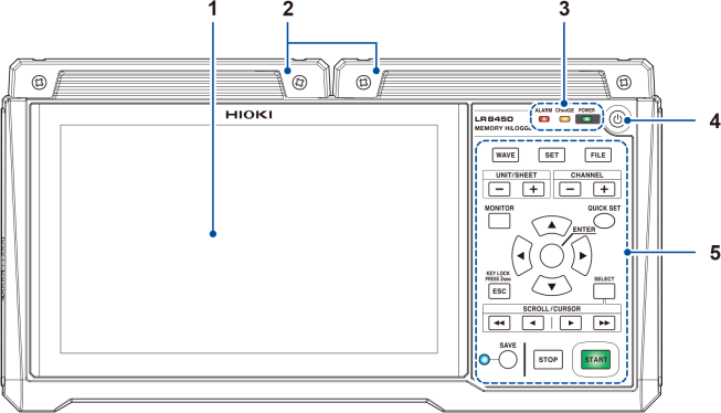
Display The instrument features a 7-inch TFT color LCD. |
||||||||||||
|
2 |
Inside each cover are connectors for plug-in modules. Affix the covers when not installing plug-in modules. The covers can also be used as connector covers for plug-in modules. |
||||||||||||
|
|||||||||||||
|
4 |
Power key Turns the instrument on or off. |
||||||||||||
|
5 |
Key controls See following page. |
||||||||||||


|
Key |
Name and functionality |
|---|---|
|
|
key Displays the waveform/value screen. Allows you to view waveforms and numerical values. “3 Start measurement” under “How to operate the instrument” in Setting Example (Measuring Temperature Using Thermocouples). |
|
|
key Displays the settings screen. Allows you to configure function settings. |
|
|
key Displays the file list screen. Allows you to perform file operations. |
|
|
keys Allows you to select the module or sheet and switches between sub tabs. |
|
|
keys Switches channels. |
|
|
key Displays the monitor. Allows you to check the current input channel. “1.11 Checking Input Signals (Monitor Function)” in the Instruction Manual. |
|
|
key Launches the configuration navigator to display the connection guide. Using the configuration navigator, you can easily configure various settings. |
|
|
, , , and keys Moves the focus* on the screen up and down. *: Refers to the active item. The background of the selected item will turn yellow. |
|
key Accepts the settings you have made. Moves down a level. |
|
|
|
key Cancels the operation. On the settings screen, moves up a level. You can disable keys by pressing and holding key for at least 3 seconds. |
|
|
key Toggles between waveform scrolling and A/B cursor movement. On the file screen, opens a menu of file operations. “Moving waveforms (scrolling)” in the Instruction Manual. |
|
|
keys Scrolls the waveform or move the A/B cursors. “Moving waveforms (scrolling)” in the Instruction Manual. |
|
|
Saves the data. The LED next to the key will turn blue while data is being saved. |
|
|
key Starts measurement. The key will turn green while measurement is in progress. |
|
|
key Stops measurement. |


Rear
|
No. |
Name and functionality |
|---|---|
|
1 |
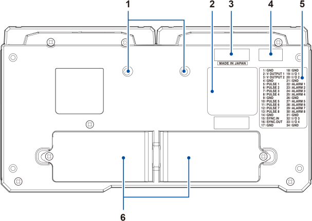
Installation screw holes The screws can be used for attaching the Z5040 Fixed Stand, which allows the product to mount on a wall. When you want to embed the LR8450 in another piece of equipment |
|
2 |
Warning Contains important information about the instrument. |
|
3 |
For the latest information, check Hioki’s website. Do not remove this sticker because the number is required for product tracking. Communicate this number when you contact your authorized Hioki distributor or reseller. This label also indicates whether the instrument is an LR8450 or an LR8450-01. |
|
4 |
Indicates the MAC address assigned to your instrument. Do not remove this sticker as the number is important. |
|
5 |
External control terminal names Indicates the names of the external control terminals on the left side of the instrument. |
|
6 |
Battery compartments Provides internal space for the Z1007 Battery Pack. (Up to 2) |
|
Left side
|
Right side
|
|
No. |
Name and functionality |
|---|---|
|
1 |
Air vents Provides ventilation to keep the instrument from reaching too high an internal temperature. |
|
2 |
External control terminals*1 Allows you to control the instrument using external signals. Outputs alarm signals. |
|
3 |
Cable hook Pass the Z1014 AC Adapter’s cable through this hook to keep it from being pulled out. Supplying power to the instrument with the AC Adapter (AC power) |
|
4 |
Connect the included Z1014 AC Adapter here. You can externally supply power (10 V to 30 V DC) here. |
|
5 |
USB connector Connect the included USB cable here. (USB 2.0 Mini-B) “9.2 Configuring and Establishing a USB Connection” in the Instruction Manual. |
|
6 |
Connect an optional USB Drive or a commercially available keyboard or mouse. (USB 2.0 Standard-A) |
|
7 |
Connect a LAN cable here. (100Base-TX/1000Base-T) “9.3 Configuring and Establishing a LAN Connection” in the Instruction Manual. |
|
8 |
Insert an optional SD Memory Card here. |
- *1
How to check the pin assignments of the external control terminals
Press the key, and choose . Names of the external control terminals will be displayed.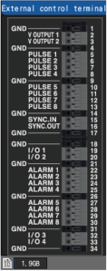
Pulse input
Pin number: 5, 6, 7, 8, 10, 11, 12, 13
Signal name: PULSE 1 to PULSE 8
Warning output
Pin number: 22, 23, 24, 25, 27, 28, 29, 30
Signal name: ALARM 1 to ALARM 8
Voltage output
Pin number: 2, 3
Signal name: V OUTPUT 1, V OUTPUT 2
External control
Pin number: 19, 20, 32, 33
Signal name: I/O 1 to I/O 4
Connecting external control signals
GND
Pin number: 1, 4, 9, 14, 17, 18, 21, 26, 31, 34
Signal name: GND
Synchronization
Pin number: 15, 16
Signal name: SYNC.IN, SYNC.OUT
Connecting external control signals
“8 External Control (Ext. I/O)” in the Instruction Manual.
|
No. |
Item |
Icon |
Description |
|---|---|---|---|
|
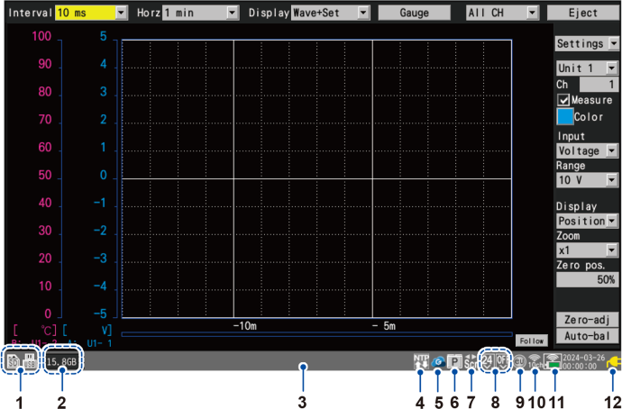
1 |
Media*1 |
|
An SD Memory Card has been inserted. |
|
|
A USB Drive has been inserted. |
||
|
2 |
Media indicator |
|
Indicates SD Memory Card and USB Drive status with a level meter. Available space is displayed as a value. The indicator turns red when available space falls to 5% or less. |
|
3 |
- |
Displays messages, icons, media space, day, and time. |
|
|
4 |
Sampling correction |
|
Indicates the sampling correction function enabled. |
|
|
Indicates the sampling correction function disabled. “Synchronizing the time”in the Instruction Manual. |
||
|
5 |
GENNECT Cloud |
|
(Gray) GENNECT Cloud is not connected. “9.11 Linking the instrument with GENNECT Cloud”in the Instruction Manual. |
|
|
(Blue) GENNECT Cloud is connected. “9.11 Linking the instrument with GENNECT Cloud”in the Instruction Manual. |
||
|
|
A file is being uploaded to GENNECT Cloud. “9.11 Linking the instrument with GENNECT Cloud”in the Instruction Manual. |
||
|
6 |
Synchronization |
|
Indicates that the instrument has been set as the primary instrument. “8.3 Configuring Sync Input/Output (SYNC) Terminals” in the Instruction Manual. |
|
|
Indicates that the instrument has been set as a secondary instrument. “8.3 Configuring Sync Input/Output (SYNC) Terminals” in the Instruction Manual. |
||
|
7 |
SCROLL CURSOR |
|
Tapping the keys moves the waveforms. “Moving waveforms (scrolling)” in the Instruction Manual. |
|
|
Tapping the keys moves the A/B cursors. “1.14 Using the A/B Cursors” in the Instruction Manual. |
||
|
8 |
Voltage output*2 |
|
No voltage is being output from the voltage output terminals. |
|
|
A voltage of 5 V DC is being output from the voltage output terminals. |
||
|
|
A voltage of 12 V DC is being output from the voltage output terminals. |
||
|
|
A voltage of 24 V DC is being output from the voltage output terminals. |
||
|
9 |
Scaling |
|
Scaling is enabled for one or more channels. “1.7 Using the Scaling Function” in the Instruction Manual. |
|
10 |
|
In station mode. (communicating) “9.4 Using Wireless Modules (LR8450-01 Only)” in the Instruction Manual. |
|
|
|
In station mode. (disrupted) “9.4 Using Wireless Modules (LR8450-01 Only)” in the Instruction Manual. |
||
|
|
In access point mode. “9.4 Using Wireless Modules (LR8450-01 Only)” in the Instruction Manual. |
||
|
|
In wireless module connection mode. The channel numbers represent the frequency band channels of the wireless LAN. “9.4 Using Wireless Modules (LR8450-01 Only)” in the Instruction Manual. |
||
|
11 |
Wireless module communications status*3 |
|
Communications between the instrument and wireless unit: Interrupted (Displays the power and signal strength status of the wireless modules during communications.) |
|
|
Communications between the instrument and wireless unit: Communicating Upper row: Signal strength Lower row: Power of the wireless module |
||
|
Signal strength*4 (Upper row) |
|||
|
|
Signal strength between the instrument and the wireless module: Excellent |
||
|
|
Signal strength between the instrument and the wireless module: Good |
||
|
|
Signal strength between the instrument and the wireless module: Fair |
||
|
|
Signal strength between the instrument and the wireless module: Poor |
||
|
Power*4 (Lower row) |
|||

|
Running on AC Adapter power. The icons will also be displayed when the modules are running on externally supplied power. |
||

|
Running on battery power (fully charged). |
||

|
Running on battery power. The battery starts to run out. Connect the AC Adapter to charge the battery. |
||

|
Running on battery power. The battery has run out. Immediately connect the AC adapter to charge the battery. |
||
|
12 |
Instrument power*5 |
|
Running on AC Adapter power. The icons will also be displayed when the modules are running on externally supplied power. |
|
|
Running on battery power (fully charged). |
||
|
|
Running on battery power. |
||
|
|
Running on battery power. The battery starts to run out. Connect the AC adapter to charge the battery. |
||
|
|
Running on battery power. The battery has run out. Connect the AC adapter to charge the battery. |
||
|
|
Running on AC Adapter power. The battery is being charged. |
||
|
|
A battery anomaly has occurred. Immediately stop the use of the instrument and remove the Battery Packs. |
||


- *1
The amount of available space on the media that is selected as the preferred auto save location is displayed to the right of the media’s icon.
- *2
The left icon indicates the state of the voltage output terminal 1: the right, that of the voltage output terminal 2.
- *3
The icon’s border will flash red for wireless module from which no measurement data is being received.
- *4
The power and signal strength status of each wireless module will be displayed using a two-tier icon.
When the multiple wireless modules are registered, they show in the module number order from the left.
- *5
Two icons will appear if two Z1007 Battery Packs have been inserted. The icon on the right indicates the status of the Battery Pack on the right when the instrument is viewed from the front (looking at the LCD screen), while the icon on the left indicates the status of the Battery Pack on the left.