Setting Example (Measuring Temperature Using Thermocouples)
This section describes how to configure the settings to measure temperature with the instrument and a plug-in module
You can measure temperature with the following products.
Preparing for measurement
How to operate the instrument
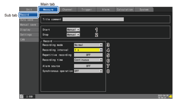
Set the recording conditions as follows:
|
No. |
Setting |
Condition |
Description |
|---|---|---|---|
|
1 |
|
|
Starts recording when the corresponding key is operated. |
|
2 |
|
|
Stops recording when the corresponding key is operated. |
|
3 |
|
|
Fixed. |
|
4 |
|
|
Measures temperatures every 1 s. |
|
5 |
|
|
Disables the repetitive recording. The instrument will perform a series of measurements only once. |
|
6 |
|
|
Continues the recording until you press the key. |
|
7 |
|
|
Disables the alarm function. |
|
8 |
|
|
Does not use synchronous operation. |
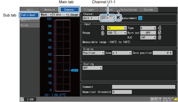
The instrument represents the input channels as Un-m.
n represents the module number; m represents the channel number.
Set the input conditions of U1-1 (Channel 1 of Module 1) as follows:
|
No. |
Setting |
Condition |
Description |
|---|---|---|---|
|
1 |
Check box |
|
Performs measurement for channels whose check box is selected. |
|
2 |
Input type |
|
Measures temperature using thermocouples. |
|
3 |
|
|
Measures temperature between -100°C and 100°C. |
|
4 |
|
|
Select Type K thermocouple. |
|
5 |
|
|
Disables the thermocouple wire break detection function. |
|
6 |
|
|
Performs the reference junction compensation in the measurement module. |

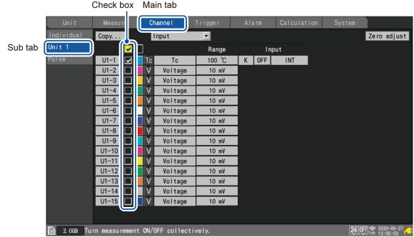
Switching over to the sub tab allows you to configure the settings for 15 channels at once.
Clear the check boxes of channels U1-2 to U1-15, exempting the channels from the measurement subjects.
|
|
Press the key. |

The confirmation window will appear.
Select , and then press the key to start measurement.
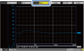
Wave+Set screen
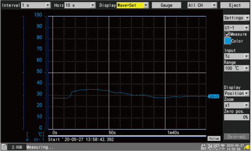
You can use the key to switch the screen.
|
Wave screen
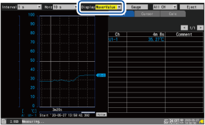
|
Wave+Value screen
|
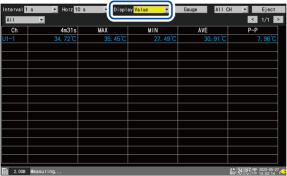
|
Value screen
|
Alarm screen
|
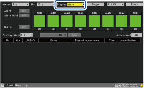
When is on, the and screens will also be displayed.
“1.15 X-Y Compositing” in the Instruction Manual.
|
|
Press the key. |

The confirmation window will appear.
Choose , and then press the key to stop measurement.
When you press the key, the file saving window will appear.
Under , select . Under , select .
Press the key while is selected.
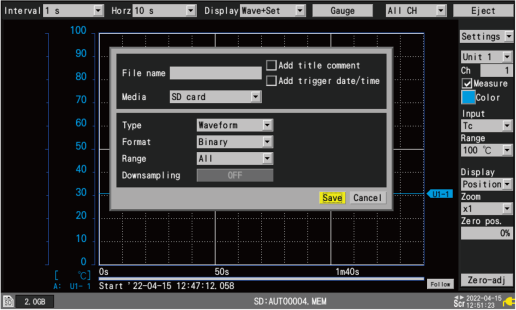
The instrument can load binary-form (LR8450-specific-form) waveform data only.
When you do not name files, the instrument will automatically name them.
Waveform data is saved in the > > > folder.
(yy-MM-dd represent the year, month, and date, respectively)
Press the key while files are selected. The data loading window will be displayed.
Select and then press the key. The instrument will load the files.
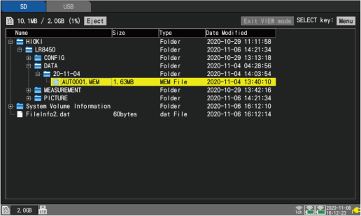
Each data is saved in the following folders:
-
CONFIG: setting data
-
DATA: waveform data
-
MEASUREMENT: numerical calculation results
-
PICTURE: image data