Connecting external control signals
This section describes how to connect external control signals to the instrument’s external control terminals. You can choose functions using sync I/O and external I/O.
Sync input, sync output: You can simultaneously operate multiple instruments.
“8.3 Configuring Sync Input/Output (SYNC) Terminals” in the Instruction Manual.
External input: You can control when to start and stop the instrument and input trigger signals.
“8.4 Configuring External Input/Output (I/O) Terminals” in the Instruction Manual.
External output: You can output signals when a trigger is activated.
“Trigger output” in the Instruction Manual.
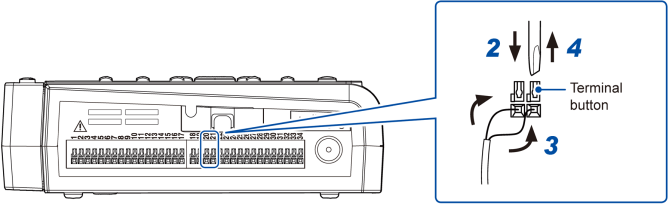
You will need: a flat-head screwdriver (with a tip width of 2.6 mm) and an input cable (for pulse measurement)
Recommended wire diameter
|
Single-wire |
Diameter of 0.32 mm to 0.81 mm (AWG 28 to 20) |
|---|---|
|
Stranded wire |
0.08 mm2 to 0.52 mm2 (AWG 28 to 20) |
|
Standard stripping length |
10 mm |
The cable will be locked in place. Pull gently on the cable and verify that it does not come out.
There are 10 GND terminals. The wire can be connected to any of the GND terminals.
The cable will be locked in place. Pull gently on the cable and verify that it does not come out.
Example connecting to external input 2 and GND
How to check the pin assignments of the external control terminals
Press the key, and choose . Names of the external control terminals will be displayed.