Wireless modules
Figures show the LR8530 Wireless Voltage/Temp Unit.
|
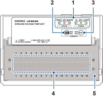
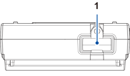
Front
|
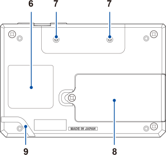
Rear
|
|
No. |
Name and functionality |
|---|---|
|
Remains on during communications. Blinks during registration or low-signal state. Lights up when an error occurs. Remains on during measurement. |
|
|
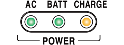
Lights up when the instrument is being powered by the AC Adapter or by an external power supply. Lights up when the instrument is operating on battery power. Blinks when the battery is low. Lights up when the Battery Pack is being charged. |
|
|
2 |
Resets the wireless module’s communications settings. Automatically configures communications settings between the LR8450-01 and the wireless modules. |
|
3 |
|
|
4 |
Input terminals Provides input terminals for each channel. The numerics represent the channel numbers. |
|
5 |
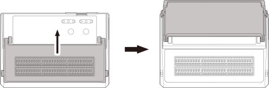
Close the cover during measurement. |
|
6 |
Warning Contains important information about the wireless module. |
|
7 |
Installation screw holes Accommodates screws for use in mounting the module on a board or wall. |
|
8 |
Battery compartment Provides space for the Z1007 Battery Pack. |
|
9 |
Cable guide Hitch the Z1008 AC Adapter’s cord to prevent the cord unplugged. Supplying power to the instrument with the AC Adapter (AC power) |


The LR8531 Wireless Universal Unit has the power terminal for the Z2000 Humidity Sensor.
Connecting the Humidity Sensor
The LR8534 Wireless Strain Unit has the DIP switch, used to select the wiring method.
Connecting a strain gage or converter
The LR8535 Wireless CAN Unit has two LEDs that indicate its operational status. The CAN Unit does not have a terminal block cover.
To perform zero-adjustment on the LR8536 Wireless Current Module, quickly press the key twice. The Current Module does not have a terminal block cover.
|
Top
|
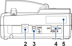
Right side
|
|
No. |
Name and functionality |
|---|---|
|
1 |
Wireless LAN Adapter Connect the Z3230 or Z3231 Wireless LAN Adapter (wireless module accessory) here. |
|
2 |
Plug the supplied Z1008 AC Adapter. You can externally supply power (10 V to 30 V DC) here. |
|
3 |
GND Serves as the function ground terminal. |
|
4 |
switch Turns the instrument on or off. |
|
5 |
For the latest information, check Hioki’s website. Do not remove this sticker because the number is required for product tracking. Communicate this number when you contact your authorized Hioki distributor or reseller. |