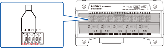
Connecting a strain gage or converter
Applicable modules: U8554, LR8534
You will need: a flat-head screwdriver (with a tip width of 2.6 mm) and either a strain gage or a strain gage-type converter
Recommended wire diameter
|
Single-wire |
Diameter of 0.32 mm to 1.29 mm (AWG 28 to 16) |
|---|---|
|
Stranded wire |
0.2 mm2 to 0.52 mm2 (AWG 24 to 20) |
|
Standard stripping length |
9 mm |
-
Choose a strain gage whose gage resistance value is 120 Ω. If you plan to use a 350 Ω strain gage, add a separate bridge box and use the same connection as for the 4-gage method (converter).
-
Choose a strain gage-type converter that supports a bridge voltage of 2 V DC.
-
For more information about measuring strain, see “11.2 Measuring Strain” in the Instruction Manual.
|
CAUTION |
|---|
|
Do not bend, pull on, or twist cables, including where they connect, excessively. Doing so could cause a wire break into the cable. |
-
Keep the cables away from power lines and ground lines.
-
When measuring with a voltage range of 5 mV or less, measurement may be affected by the thermal electromotive force of wires and connectors.
-
Perform auto-balancing using the same wires and connectors as will be used in measurement.
-
All channels in the U8554 and LR8534 terminal block have a common E terminal (GND).
-
If connecting the lead wires for the strain gage or other sensor directly, strip back about 9 mm of insulation from the tip of each lead wire first.
-
When using a strain gage, connect lead wires of the recommended wire diameter using the gage terminals or use a strain gage with lead wires of the recommended wire diameter.
-
If the sensor has a connector (NDIS connector, etc.) like a strain gage-type converter, use the connection cable supplied by the sensor manufacturer to connect it.
Affixing connection confirmation labels
Affix the included connection confirmation labels as desired (for example, on the back of the terminal block cover).
|
If label is affixed to the terminal block cover
|
Connection confirmation label
|
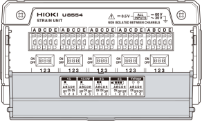
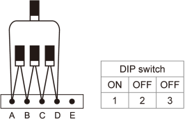
Setting the DIP switches for input connections
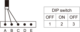
Example: 1-gage method (2-wire setup)
The cable will be locked in place. Pull gently on the cable and verify that it does not come out.
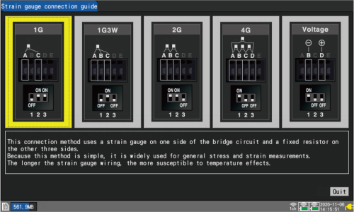
How to display the strain gage connection guide
Press the key, and choose . The strain gage connection diagrams will be displayed.
“1.16 Configuration Navigator (Quick Set)” in the Instruction Manual.
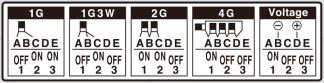
Setting the DIP switches for input connections
This section describes how to set the DIP switches for input connections.
The DIP switch is on in the upper position and off in the lower position.
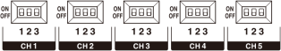
DIP switches
|
(1) 1-gage method (2-wire setup)
|
(2) 1-gage method (3-wire setup)
|
|
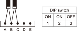
(3) 2-gage method (adjacent sides)
|
(4) 4-gage method/converter
|
|
(5) Voltage input
|
|
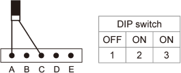
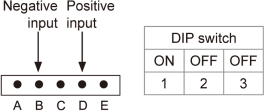
When connecting a converter, the terminals function as indicated below.
If the converter output utilizes a connector (such as NDIS connector), use a cable with a connector on one end and loose wires on the other to make the connection.
A Applied voltage (+)
B Converter output (-)
C Applied voltage (-)
D Converter output (+)
E Measurement GND
Measuring strain
-
After installing the strain gage and completing its wiring, perform auto-balancing before measurement.
“Measuring strain”in “1.4 Configuring Input Channels” in the Instruction Manual.
-
Secure the strain gage wires in place and ensure that the gage itself is not subjected to force.