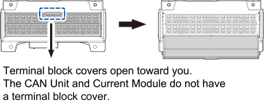
Plug-in modules
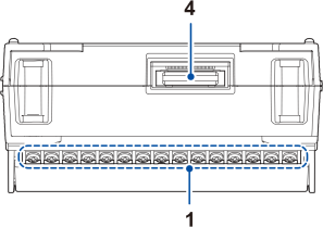
Figures show the U8550 Voltage/Temp Unit.
|
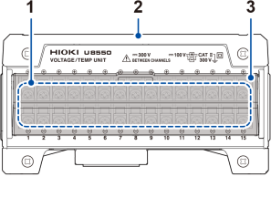
Front
|
Top
|
|
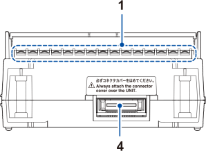
Rear
|
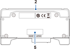
Bottom
|
|
No. |
Name and functionality |
|---|---|
|
1 |
Input terminals Provides input terminals for each channel. The numerics represent the channel numbers. |
|
2 |
Connector cover Protects the plug-in unit’s input terminals. |
|
3 |
Close the cover during measurement. |
|
4 |
Connector Used for module expansion. Attach the connector cover to any unused connectors. |
|
5 |
For the latest information, check Hioki’s website. Do not remove this sticker because the number is required for product tracking. Communicate this number when you contact your authorized Hioki distributor or reseller. |
The U8554 Strain Unit has the DIP switch, used to select the wiring method.
Connecting a strain gage or converter
The U8555 CAN Unit has two LEDs that indicate its operational status.
|
If four plug-in modules have been installed
|