Using the Scaling Function
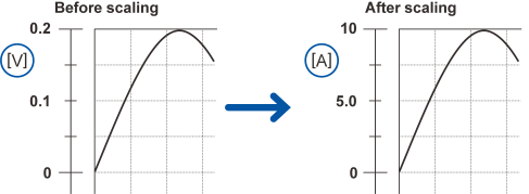
This section describes how to use the scaling function to convert voltage values measured by the instrument into the measurement target’s physical properties (current, temperature, etc.) and then display or record them.
Converted values can be displayed using decimal or scientific notation.
Example: With slope = 50 and unit = A:
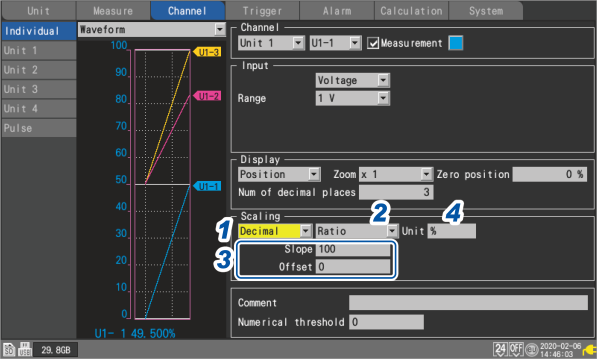
1 Select the scaling display method.
|
OFF ☑
|
Does not use the scaling function.
|
|
Decimal
|
Displays converted values as decimals.
|
|
Exponent
|
Displays converted values as exponents.
|
2 Select the scaling conversion method.
|
Ratio ☑
|
Sets the physical quantity (conversion ratio) per 1 V of input signal and the offset.
|
|
2-point
|
Sets converted values for two input signal voltage values.
|
|
Sensitivity
|
Sets the sensitivity constant for a heat flow sensor or actinometer.
|
|
Rating
|
Sets the rated capacity and rated output according to values in the inspection results sheet for the strain gage-type converter.
(Available only when the U8554 or LR8534 Strain Unit is used)
|
The conversion method cannot be selected for pulse integration measurement.
Scaling settings during integration measurement
3 (When the scaling conversion method is set to [Ratio])
Enter the slope and the offset in [Slope] and [Offset], respectively.
Select the numerical value entry item and press the ENTER key to display the numerical value setting window.
“Value entry method” in “1.1 Performing Basic Operations” in the Instruction Manual.
-9.9999e+09 to +9.9999e+09
Example setting
Make measurements using a differential probe with a division ratio of 1/100 and display waveform data as values expressed in units of volts (V):
|
Unit
|
V
|
|
Slope
|
100
|
|
Offset
|
0
|
4 Enter the post-conversion unit in [Unit] (up to 7 single-byte characters).
“Text entry method” in “1.1 Performing Basic Operations” in the Instruction Manual.
5 (When the scaling conversion method is set to [2-point])
Enter the pre- and post-conversion values in [Convert 1] and [Convert 2], respectively.
Select the numerical value entry item and press the ENTER key to display the numerical value setting window.
-9.9999e+29 to +9.9999e+29
Example setting
Convert 4-20 mA output from a sensor into 0 to 100 mm.
The 4-20 mA output is measured as 1 V to 5 V using a 250 Ω shunt resistor.
Convert a range of 1 V to 5 V into that of 0 mm to 100 mm.
|
Unit
|
mm
|
|
Convert 1
|
Convert 1 into 0 (1 V into 0 mm).
|
|
Convert 2
|
Convert 5 into 100 (5 V into 100 mm).
|
6 (When the scaling conversion method is set to [Sensitivity])
Enter the sensitivity value in [Sensitivity].
Select the numerical value entry item and press the ENTER key to display the numerical value setting window.
-1.0000e+09 to +1.0000e+09
Example setting
Make measurements using a heat flow sensor with a sensitivity constant of 0.02421 mV/W•m-2 and display waveform data as values expressed in units of watts per square meter (W/m2):
|
Unit
|
W/m2
|
|
Sensitivity
|
0.02421 m (displayed as 24.21 μ)
|
|
Offset
|
0
|
7 (When the scaling conversion method is set to [Rating])
(Available only when the U8554 or LR8534 Strain Unit is used)
Enter the rated capacity and rated output in [Capacity] and [Output], respectively.
Set the rated capacity and rated output*1 (μV/V) according to values in the inspection results sheet for the strain gage-type converter.
Enter the rated capacitance unit as the unit.
Select the numerical value entry item and press the ENTER key to display the numerical value setting window.
+1.0000e−09 to +9.9999e+09
|
Specify the parameters such that the quotient of the rated capacity divided by two times the rated output is less than or equal to 9.9999E+9.
|
For the rated capacity and rated output, see an inspection record of a strain gauge converter to be used.
- *1
Some inspection reports may provide the rated output in two representations: the one expressed in microvolts per volt (μV/V) and the other expressed as a dimensionless quantity multiplied by 10 to the −6th power strain (×10-6 strain, με).
In such a case, enter the quantity in microvolts per volt.
Example setting
If you wish to display measured results obtained using an acceleration sensor with a rated capacity of 20 G and rated output of 1000 μV/V as values expressed in units of gees (G):
|
Unit
|
G
|
|
Capacity
|
20
|
|
Output
|
1000 (displayed as 1k)
|
You can use [Scaling] on the settings list screen to configure the settings.
“1.9 Configuring Channels in a List” in the Instruction Manual.
-
Setting the display position (upper and lower limit values)
When using the scaling function, configure scaling before setting the upper and lower limit values.
“Setting upper and lower limit values” in “1.6 Configuring the Waveform Display” in the Instruction Manual.
-
Setting of the number of display digits
While using the scaling function, you can set the display digit. (Default setting: three decimal places)
“Configuring the display of the vertical axis” in “1.6 Configuring the Waveform Display” in the Instruction Manual.
-
Reviewing pre-conversion waveforms
When you save waveform data in the binary format, raw data (data prior to the scaling conversion) and scaling settings are recorded. Loading waveform data allows waveforms after the scaling conversion to be displayed. You can review the pre-conversion waveforms if you turn off the scaling setting.
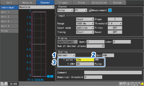
Scaling settings during integration measurement
You can use the scaling function to convert the integrated pulse count to the measurement target’s physical properties (watt hours, volt-amperes, etc.) and then display or record the result.
The pulse output device will have predetermined physical quantity that corresponds to 1 pulse or a number of pulses that corresponds to a value of one in the basic units (for example, 1 kWh, 1 L, 1 m3).
1 Select the scaling display method.
|
OFF ☑
|
Does not use the scaling function.
|
|
Decimal
|
Displays converted values as decimals.
|
|
Exponent
|
Displays converted values as exponents.
|
2 Enter the post-conversion unit (up to 7 single-byte characters).
“Text entry method” in “1.1 Performing Basic Operations” in the Instruction Manual.
3 Enter physical quantity per pulse or the number of pulses (example: 1 c = 1 pulse) that corresponds to a value of one in the basic units.
Select the numerical value entry item and press the ENTER key to display the numerical value setting window.
The settings that define the physical property per pulse and the number of pulses corresponding to a value of one in the basic units are linked.
Example setting
When connecting a watt-meter with 50,000 pulses per kWh and integrating its output
|
Scaling
|
Decimal
|
|
Unit
|
kWh
|
|
1 kWh
|
50000 (number of pulses per kWh)
|
When connecting a flowmeter with 10 L per pulse and integrating its output
|
Scaling
|
Decimal
|
|
Unit
|
L
|
|
1 pulse
|
10 (flow rate [L] per pulse)
|
Configuring the scaling of the U8556/LR8536 Current Module
You can use the scaling function to convert measured current values to 1-phase 2-wire power values.
Let V denote the voltage, λ the power factor, I the current, the power can be expressed by W = V × λ × I
1 Choose between two scaling display options: [Decimal] and [Exponent].
2 Select [Ratio] as the scaling conversion method.
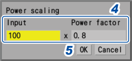
3 Press the ENTER key while [Power] is selected.
The power scaling screen is displayed.
4 Enter the voltage V and the power factor λ in the [Input] and [Power factor] boxes, respectively.
Example setting
For a voltage of 100 V, a power factor of 80%
|
Input
|
100
|
|
Power factor
|
0.8
|
5 Press the ENTER key while [OK] is selected
The slope, offset, and unit (W) is automatically set.
Configuring the scaling of the U8554/LR8534 Strain Unit
Strain gage-type converter
You can use values on the Strain gage-type converter’s inspection record to convert the converter’s output into physical quantities.
Two methods are available: using a calibration factor*1 and using rated capacity and rated output. If all these values are listed, either method can be used.
When an inspection record provides a calibration factor
Example setting
To display waveform data measured using a strain gauge converter having a calibration factor of 0.001442 G /1 × 10-6 strain*2 as figures in gravities (G)
|
Scaling
|
Decimal
|
|
Conversion method
|
Ratio
|
|
Unit
|
G
|
|
Slope
|
0.001442 (Indicated as 1.442 m)
|
|
Offset
|
0
|
- *1
Some inspection reports may provide a calibration factor in two representations: the one in per one microvolt per volt (/1 μV/V) and the other in per 1 multiplied by 10 to the -6th power strain (/1×10-6 strain).
In such a case, enter the quantity expressed in per 1 multiplied by 10 to the .6th power strain (/1×10-6 strain).
- *2
10-6 strain = με
When an inspection record provides rated capacity and rated output
(When the scaling conversion method is set to [Rating])
Strain gage
To convert values measured using strain gages into strain, determine the scaling conversion ratio using the following corrections:
Also, make the following corrections as required:
“11.2 Measuring Strain” in the Instruction Manual.