Trigger Function
Triggers provide functionality for starting and stopping measurement based on specific conditions and signals.
When a specific condition (a trigger condition) occurs, the trigger is said to activate.
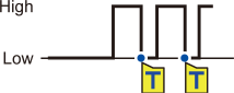
The points at which triggers activate (i.e., the points in time at which trigger conditions are satisfied) are known as trigger points, which are identified by the  mark.
mark.
When a trigger activates, you can start or stop recording.
Trigger sources can be selected from among the following:
-
Analog triggers (level, window)
-
Pulse (level, window)
-
Logic triggers (condition, pattern)
-
Waveform calculation (level, window)
-
CAN (level, window, logic)
-
Interval triggers
-
External triggers
The instrument allows the following specific conditions to be set:
|
Specific condition |
Description |
|---|---|
|
Start trigger |
Starts recording when the trigger condition is satisfied. Example: Start recording when the temperature reaches or exceeds 50°C. |
|
Stop trigger |
Stops recording when the trigger condition is satisfied. Example: Stop recording if a signal falls below 1 V. |
|
External trigger |
Allows you to activate a trigger using an external signal. (I/O 3) Example: Control recording based on the operation of other devices. “2.6 Applying Triggers Based on External Sources” in the Instruction Manual. |
|
Pre-trigger |
Records data before the trigger point. Example: Record a phenomenon that precedes an anomaly. |
|
Interval trigger |
Applies the trigger at a set interval. Example: Record data at one-hour intervals. “2.7 Activating a Trigger at a Set Interval” in the Instruction Manual. |
|
Trigger activation conditions |
You can set the conditions under which the trigger will activate. Select AND/OR operation between triggers. |
IMPORTANT
-
If the trigger function is , you can start recording by pressing the key. (Free-run)
-
If the trigger function is , the instrument will remain in the “trigger standby” state until the trigger condition is satisfied. Recording will start when the trigger condition is satisfied.
-
The “trigger standby” interval will be shown on the monitor screen.
“1.11 Checking Input Signals (Monitor Function)” in the Instruction Manual.
-
During communications disruption, wireless modules cannot judge whether the trigger conditions are satisfied. When the trigger conditions have been satisfied on completion of data recovery following reestablish communications, the trigger will activate.
-
When the stop trigger condition is satisfied during data recovery, data points after this point will be regarded as .
“11.14 Data Handling During Communications Disruption” in the Instruction Manual.
-
While the pre-trigger setting is enabled, the recovered data cannot activate the trigger. In addition, data acquired during the trigger standby state cannot be recovered.
-
The next trigger will not be accepted while trigger processing remains in progress. Trigger output will be active while trigger processing is in progress.
“Trigger output” in “8.4 Configuring External Input/Output (I/O) Terminals” in the Instruction Manual.
Trigger Meanings
This section describes how to set start or stop conditions for measurement.
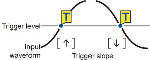
You do so by setting the type of trigger (level, window, or pattern) and the slope (signal rising or falling).
Trigger types
The following three types of triggers are provided:
|
Type |
Operation |
Description |
|
|---|---|---|---|
|
Level trigger |
↑ |
|
Activates when the waveform becomes equal to or exceeds the set level while rising. |
|
↓ |
Activates when the waveform falls below the set level value. However, the trigger cannot activate when the waveform becomes equal to the value while falling. *1 |
||
|
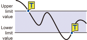
Window trigger |
IN |
|
Activates when the waveform enters the range defined by a pair of upper and lower limit values. As well, the trigger activates when the waveform becomes equal to the upper limit value while falling and the lower limit value while rising. |
|
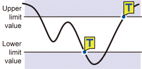
OUT |
|
Activates when the waveform exits the range defined by a pair of upper and lower limit values. However, the trigger cannot activate when the waveform becomes equal to the upper limit value while rising or the lower limit value while falling. *2 |
|
|
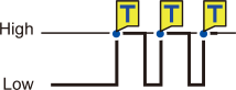
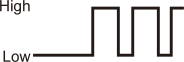
Pattern trigger |
1 |
|
Activates when a logic signal changes to 1. |
|
0 |
|
Activates when a logic signal changes to 0. |
|
|
X |
|
Ignores the signal. No trigger will activate. |
|
- *1
For pulse channels, only if the level value is set at zero, the trigger can also activate when the pulse becomes equal to zero while falling.
- *2
For pulse channels, only if the lower limit value is set at zero, the trigger can also activate when the pulse becomes equal to zero while falling. As well, only if the upper limit value is set at zero, the trigger can also activate when the pulse becomes equal to zero while rising.