Configuring Alarms (Alarm Output)
This chapter describes how to set alarm conditions for each measurement channel.
You can have the instrument sound a tone or output an alarm signal to an external device when measurement data satisfies the set condition.
For example, you can output an alarm when the recorded temperature becomes too high.
The following channels can be set as an alarm source:
analog, pulse, logic, waveform calculations, and CAN.
The following types of alarms can be set: level, window, slope, and pattern. Up to 100 alarm conditions can be set for CAN channels.
Alarm signals can be outputted from the external control terminals to external devices.
“8 External Control (Ext. I/O)” in the Instruction Manual.
If an alarm condition is satisfied when measurement starts, the alarm will be output immediately.
IMPORTANT
The logger is unable to detect alarm conditions when there is no data due to an interruption in communication with wireless modules. However, it can detect the alarm condition of the wireless module communication interruption.
When communication is reestablished with the wireless modules, the system will recover data and detect alarm conditions.
Setting shared alarm conditions for all channels
This section describes how to set shared alarm conditions that apply to all channels.


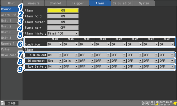

Configure each alarm channel ( to ).
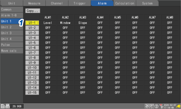
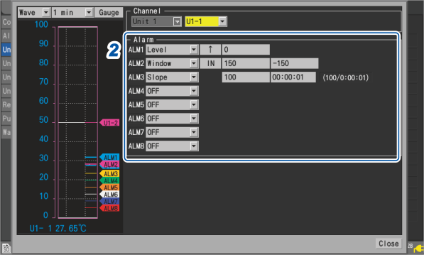
Configuring channel-specific alarm settings
This section describes how to configure alarm functionality for individual channels.
, (n = 1, 2, . . .), , or
Settings list screen
Individual settings window
|
Alarm type |
Setting description |
Operation |
Description |
|
|---|---|---|---|---|
|
☑ |
- |
- |
Disables the alarm function. |
|
|
|
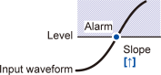
Slope |
☑, |
|
Outputs an alarm when the measurement data is greater than or equal to the specified level. |
|
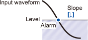
Level |
Enter a value. |
Outputs an alarm when the measurement data is less than the specified level. However, only if the pulse-channel level is specified at zero, an alarm is output when the pulse-channel measurement data is also equal to zero. |
||
|
|
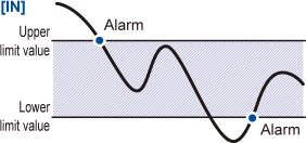
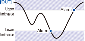
Direction |
☑, |
|
Outputs when the measurement data remain between the lower and upper limits. |
|
Upper and lower limit values |
Enter values. |
|
Outputs when the measurement data is less than the lower or more than the upper limit. However, only if the pulse-channel upper or lower limit value is specified at zero, an alarm is output when the pulse-channel measurement data is also equal to zero. |
|
|
|
Level |
Enter a value. |
|
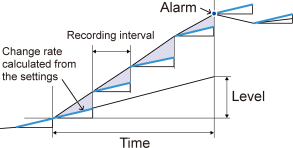
Outputs an alarm when a change rate of measured data acquired within the set period exceeds that calculated from the settings (level/time). *2 |
|
Time |
Set a time.*1 |
|||
|
|
Slope |
☑, |
|
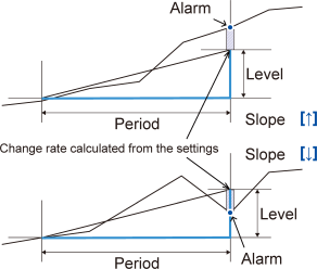
Outputs an alarm when the amount of change in the set period is greater than or less than the set level value. |
|
Level |
Enter a value. |
|||
|
Width |
Set a width with time. |
|||
|
|
Level |
, , ☑ |
|
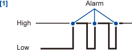
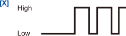
Outputs an alarm when the logic signal is (high). |
|
|
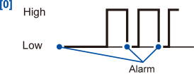
Outputs an alarm when the logic signal is (low). |
|||
|
|
Not used in alarm judgments. Ignores the signal. |
|||
- *1
Integral multiples of the data refresh interval of the module can be set for the time figure.
- *2
Slope example
With a level of 5°C and a time of 5 s
1. With a recording interval of 5 s
An alarm will be output if the current measured value differs from the previous measured value by more than 5°C.
Example data: 20°C, 25.1°C
2. With a recording interval of 1 s
An alarm will be output if each current measured value differs from its previous measured value by more than 1°C for five data points in a row.
Example data: 20°C, 21.1°C, 22.2°C, 23.3°C, 24.4°C, 25.5°C
|
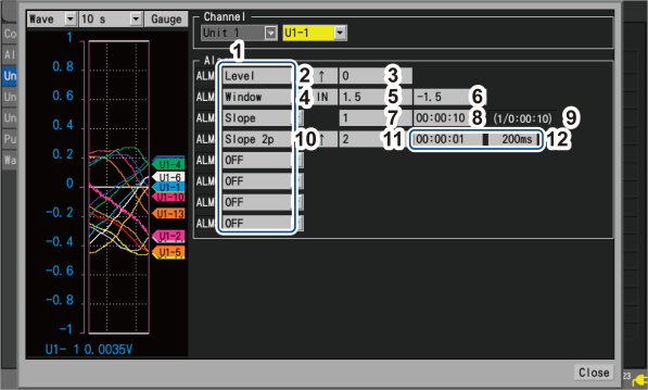
1 |
Alarm type |
|
2 |
Slope for Alarm |
|
3 |
Level for Alarm *1 |
|
4 |
Direction for Alarm |
|
5 |
Upper limit value for Alarm *1 |
|
6 |
Lower limit value for Alarm *1 |
|
7 |
Level for Alarm *1 |
|
8 |
Time for Alarm The alarm slope time cannot be set to a value that is less than 1 sec. |
|
9 |
Level and time used to judge whether alarm conditions are met (level/time)
In both cases, the level is calculated as follows: (Level) = (Value set in Box 7) × {(Time) / (Value set in Box 8)}. |
|
10 |
Slope for Alarm |
|
11 |
Level for Alarm *1 |
|
12 |
Period for Alarm A period of up to less than 24 hours and equivalent of 1000 samples can be set. |
- *1
The instrument expresses strain in terms of micro epsilon (με). You do not need to enter the SI prefix micro (μ).
Press the key while is selected.
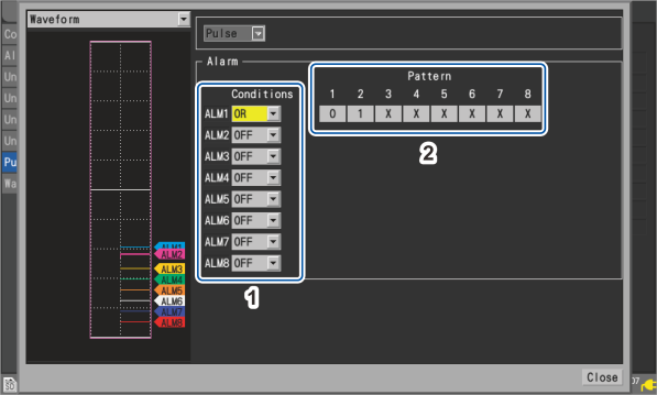
Under , select the condition for activating the alarm.
“Measuring logic signals” in “1.4 Configuring Input Channels” in the Instruction Manual.
|
|
Does not use alarms based on logic signals. |
|---|---|
|
|
Outputs an alarm when any of the patterns is satisfied. |
|
|
Outputs an alarm when all of the patterns are satisfied. |
|
1 |
Alarm activation conditions |
|
2 |
Level for Alarm |