Connecting a Non-Contact CAN Sensor
Applicable modules: U8555, LR8535
You will need: SP7001-95 Non-Contact CAN Sensor
|
CAUTION |
|---|
|
Do not connect any device other than the Non-Contact CAN Sensor to the LR8535’s USB power supply receptacle. Doing so could damage the measurement target or the instrument. |
-
If using the Non-Contact CAN Sensor, set the U8555 or LR8535’s terminator to OFF.
-
If using the Non-Contact CAN Sensor, use the U8555 or LR8535 in the ACK OFF state.
“1.5 Configuring CAN Settings” in the Instruction Manual.
On the LR8535, the cable can be connected to a USB power supply receptacle that’s designed specifically for the Non-Contact CAN Sensor.
Right side of LR8450
![]()
Bottom of LR8535
![]()
The cable will be locked in place. Pull lightly on the cable to make sure it stays connected.
For more information about how to connect the SP7001-95 Non-Contact CAN Sensor to a CAN bus, see the SP7001 Instruction Manual.
Setting the termination resistance
-
CAN communications systems require a termination resistance of 120 Ω at both ends of the bus.
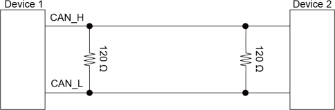
-
By enabling the U8555/LR8535’s terminal resistance setting, you can insert a 120 Ω resistance between the CAN bus differential signals inside the unit.
“11.14 Input Circuit Schematics” in the Instruction Manual.
The LEDs allows you to check the CAN unit’s operational status.
|
LED |
Status |
|---|---|
|
|
(Receive mode)
|
|
(Measured value output mode)
|
|
|
|
|


- *1
The LED will flash if any of the set CAN communications is operating according to the configured conditions.
“6.3 Receive CAN Data” in the Can Editor Instruction Manual.
- *2
Check the receive channel settings.
“6.3 Receive CAN Data” in the Can Editor Instruction Manual.
- *3
The CAN communications conditions may not match those of the CAN bus, or the CAN port may not be properly connected to the CAN bus.
“5.4 Setting the Communication Method of the CAN Unit” in the Can Editor Instruction Manual.
- *4
Check whether output has been enabled for any channel.
“7.5 Selecting the Channel to be Output” in the Can Editor Instruction Manual.